
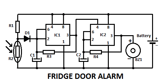
This fridge door alarm is using a 3V battery supply should be placed (in a small box) in the fridge near the lamp or close to the opening. With the door closed the photo resistor R2 presents a high resistance (>200K) thus clamping IC1 by holding C1 fully charged across R1 and D1.
When a beam of light enters from the opening, or the fridge lamp lights, the photo resistor lowers its resist ance (<2K) stopping C1 charging current. Therefore IC1, wired as an astable multivibrator, starts oscillating at a very low frequency and after a period of about 24 sec. its output pin (#3) goes high, enabling IC2.
This chip is also wired as an astable multivibrator, driving the Piezo sounder intermittently at about 5 times per second. The alarm is activated for about 17 sec. then stopped for the same time period and the cycle repeats until the fridge door closes.
Some notes for the fridge door alarm:
- Delay time can be varied changing C1 and/or R3 values.
- Beeper repetition rate can be varied changing C2 and/or R4 values.
- Stand-by current drawing: 150µA.
- Place the circuit near the lamp and take it away when defrosting, to avoid circuit damage due to excessive moisture.
- Do not put this device in the freezer.
Fridge door alarm circuit diagram

Components Values
R1 = 10K 1/4W Resistor
R2 = Photoresistor (any type)
R3 = 2M2 1/4W Resistor
R4 = 1M 1/4W Resistor
C1= 10µF 25V Electrolytic Capacitor
C2 = 100nF 63V Polyester Capacitor
D1 = 1N4148 75V 150mA Diode
IC1, IC2 = 7555 or TS555CN CMos Timer ICs
BZ1 = Piezo sounder (incorporating 3KHz oscillator)
B1 = 3V Battery (2 x 1.5V AA, AAA or smaller type Cells in series)


Mrb paylaşımın gerçekten dikkat çekici, saolun